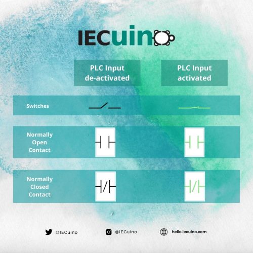
It is a bit complicated to understand the PLC Wiring, Ladder Diagram symbol combinations and their logic states when one starts with PLCs and Ladder Logic. Therefore, we will be explaining in detail how to go about it. For ease of understanding, here you have an illustration:

Referring to the image above, there are 3 types of contacts:
- Switch
- N.O. Contact
- N.C. Contact
The switch is a simple ON/OFF switch. The N.O. and N.C. contacts have already been explained in our previous posts, however, their functionality is going to be briefly explained below.
Firstly, it is essential to keep in mind that the Normally Open Contact (NO Contact) is open by default, unless in some way it closes. In the case that the NO contact closes for any reason, and you have your PLC input disconnected, the NO contact will go back to its default state, i.e, open state.
For the Normally Closed Contact (NC contact), unlike N.O. contact, it is closed by default. So, when you have your PLC input disconnected, the N.C. contact will go back to its default state (closed).
The contacts show their change of state by changing their colors from Black to green. Black is a representation of open circuit / no flow of current / False variable. Then green is a representation of closed-circuit / flow of current / True variable.
