Start with Ladder Logic in IECuino
In this post, we are going to explain to you how to start with Ladder Logic once your project is created. After that, you have to access to the working area. Within the project environment, the system displays a Ladder Diagram by default.
First of all, to start with Ladder Logic you have to create one of the following elements which you are going to work with:
- Ladder Setup
- Arduino Setup
- Ladder Diagram
- Arduino Code
- Global Variable List
- IO Mapping
- Library
- Setup
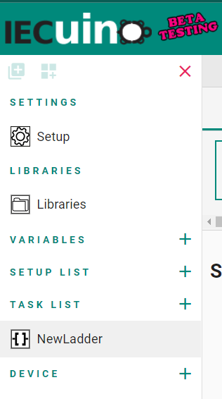
Just click on the plus icon (+) on the left and choose the element that you want to create.
Ladder Diagram for Arduino to start with Ladder Logic
How to create a Ladder Diagram
Your Ladder Diagram will be under the Task List. You just need to click on the Ladder Diagram that you want to work on to jump from one to another. When you are working on the Ladder Logic, you can add sections from the + icon in the lower right corner.
Sections
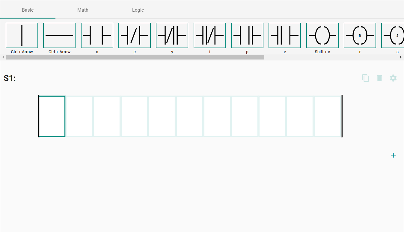
When a section is created, the icon (+) to create a new one moves just below the section created by default.
Also, you can see three icons in the upper right corner of the section created. The first one is used to clone the section. Next, as you can see, there is the delete icon, so you can remove the section from your diagram. Then, with the settings icon, you can change the name and put a description.
Contacts
Firstly, you have to know that you must install the IECuino Driver to start programming.
Just below the header, there are three tabs that will allow you to work with Basic, Math, and Logic contacts.
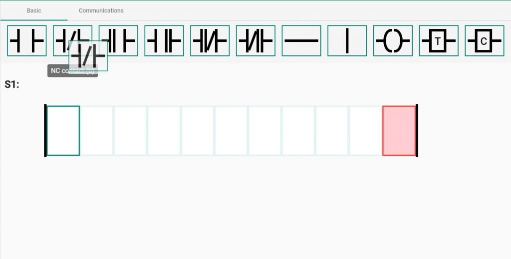
While you are working with a Ladder Diagram, you have the block icons available and ready to add to your section.
You can add blocks by dragging and dropping with a mouse or using a keyboard. Notice that you can see the keyboard shortcut to add the element to the Ladder Diagram. It is important to remember these keyboard shortcuts because it allows you to program much faster than with the mouse.
Apart from that, you must know that most of the blocks can be placed anywhere in the diagram. However, the Normally Open, Normally Closed and similar contacts can only be placed as inputs and more to the left position in the diagram, not as outputs.
Properties
When you drop an element into the diagram or select a current element, the properties of the selected element appear on the right of the interface.
You will see that there are some fields that require to be completed. That fields have this symbol: *.
You can establish a relation between the element and a global variable present in your Global Variable List file.
Furthermore, you can add comments in case you need them.

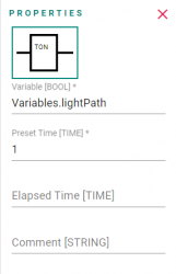
On the other hand, you must know that the fields have to be completed with a value of the required type. In the following example, we use a TON contact. As you can notice, there is a required field, but it is also essential that the value you enter is a number.
Arduino’s code for Ladder Logic in IECuino
When programming with Arduino code in the IECuino environment, take into account that you do not need to use the usual loop.
Global Variable List (GVL)
By clicking on the plus icon close to Application, you can create new elements. If you create a GVL (Global Variable List), this element will be placed below the Application slot.
By clicking on the plus icon on the right you can create the variables.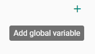
You need to write the name of the variables WITHOUT spaces.
Choose the variable type (you have 18 different variables types) and add some comments, in case you need it.
It is always good to use adequate variable names.
The variables created here will be available to use on the Ladder Diagram and the IO Mapping.

With the icons placed on the right side, you can delete or edit the variables, changing the name, type or description.

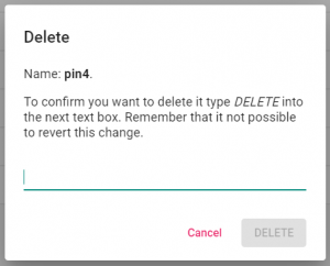
If you want to delete a variable, remember that you must always confirm it by writing DELETE.
IO Mapping of the Arduino device
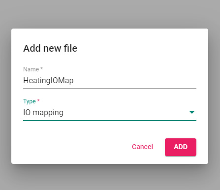
By clicking on the plus icon near to Application you can create new elements, a new File.
If you create an IO Mapping, this element will be placed below the Device slot.
Once created, you can start working with them.
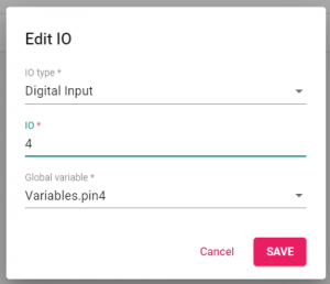
New IO Mapping
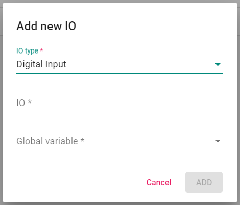
By clicking on the plus icon on the right, you can create the IO Mapping of your project.
First, you need to choose the type of Input or Output, and then the corresponding number along with the variable assigned.
Edit or Delete
With the icons placed on the right-hand side, you can delete or edit the IO Mappings, change the name, type or description.
If you want to delete an element, remember that you need always to write DELETE.
Visit the platform. Start Programming!