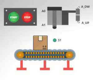
Transport and box stamping
This post is a Ladder Logic Interlocking, which is going to be about a simple example of transport and box stamping. You will see that it is similar to a previous example about valves and sensors, called Ladder Interlocking II.
As the previous example of Ladder Logic Interlocking, we must follow conditions. Firstly, let’s take a look at the required conditions:
- When the START button is pressed, the motor (M) should start and move the belt; and, if the STOP button is pressed, the whole process should stop.
- The boxes will move on the belt. If the sensor S1 detects the presence of one of them, then the motor (M) must be switched off and stop the belt.
- When the S1 sensor detects a case, the A_DW solenoid valve must be activated immediately to deploy the cylinder piston rod and stamp the case.
- The cylinder piston must retract after stamping the cases. In addition, the M motor must be turned on to move the stamped or sealed box.
Step 1: Identify the physical inputs and outputs for this Ladder Logic Interlocking
First of all, we must identify the inputs and outputs. Keep in mind that the inputs comprise the pushbuttons, sensors, switches, etc. The outputs are the actuators such as motors, cylinders, solenoid valves, indicator lights, etc.
In this case, we have 5 inputs and 3 outputs.
Inputs
Outputs
- START: I0.0
- STOP: I0.1
- S1: I0.2
- A0: I0.3
- A1: I0.4
- M: Q0.0
- A_DW: Q0.1
- A_UP: Q0.2
Step 2: Make a Ladder Logic Diagram of the physical connections
Secondly, we must make physical connections to the PLC. This will help us to know if the inputs are normally open or normally closed.
Now, we are going to construct the Ladder Diagram for the START and STOP buttons. But before we start, we must take into account the initial conditions that the process must have in order to start operating correctly.
First condition
According to the first condition, if the START button is pressed, the motor M should be turned on and the conveyor belt would start to move. If the STOP button is pressed, the conveyor belt would stop.
The cylinder piston must always be retracted at the start of the process, but power may go out while the conveyor belt is in movement and the cylinder piston does not stay retracted. So, for this not to happen, the coil must turn on and allow the cylinder piston to retract. Also, this coil must be turned off when the cylinder piston is detected by the A0 sensor.
Second condition
The second condition says that the motor (M) should turn off and move the conveyor belt. The boxes will move on the conveyor belt if the S1 sensor detects the presence of one of them. Then, the motor (M) must be turned off and the coil (M), which refers to the motor, must turn on. Also, when the S1 sensor detects the presence of a box, the motor must turn off.
Third condition
In summary, this third condition calls for coil A_DW to be energized when sensor S1 detects the box. That means that in the Ladder Diagram, contact S1 must be Normally Open, because when a signal from the sensor arrives, it changes state and closes.
We have to prevent risks. In this case, what can happen is that the coil may get stuck or self-retained. To solve this problem we must take into account that when the cylinder piston reaches the position where the A1 switch is located, it must de-energize the A_DW coil, sending a high voltage level to the PLC.
Fourth condition
For this last condition, we must know that when the cylinder piston is totally down, the A1 sensor is going to detect the presence of the cylinder piston and it is going to de-energize the A_DW coil. De-energizing the coil A_DW allows the energization of A_UP coil, and then the piston unfolds.
After the box has been stamped, the motor must turn on and move the conveyor belt to transport the box. This happens when the sensors S1 and A1 are activated.
The M coil must be embedded or self-retaining, since when the A1 sensor is deactivated because the cylinder piston starts to retract, it does not deactivate the M coil. This coil must be deactivated only when the entire box has passed in front of sensor S1. It must be deactivated because there is a line with the same label that refers to the M coil, which is activated when S1 is deactivated.
In some Ladder Logic programs, it is not allowed to use the same variable name for 2 or more coils. Moreover, it is a bad practice at the moment that we have to make the Ladder Diagram, as complications may arise in some rungs.
The most recommended solution would be to rename the variable and assign memories to it. Then, add other rungs with these new variables that, connected in parallel, can activate the M coil.
Components of this Ladder Logic Interlocking
- M1 (memory) → Its function is to turn on or off the rungs of the Ladder Diagram, but also it energizes the rungs where the same variable is located, i.e. M1. It is important to remember that the M coil represents the motor, since this is the way to move the belt to carry the box. It will energize when we push the START button.
- A_UP → Sensor. This actuator will lower the stamper to the height of the box. It will go down and at some point A1 will be activated.
- A_DW → Sensor. This actuator will raise the cylinder piston. By default, it is activated.
- A0 → As default is on and keeps the stamper up, the A0 would activate the A_UP.
- A1 → When the stamper is down, this sensor is activated and deactivates the A_DW, so the A_UP can now be activated.
- M2 (memory) → Is the easiest to activate, because it is activated by default (as long as S1 is off).
- M3 (memory) → The first M3 acts as a stopper of the A_DW, i.e. when M3 is activated, the stamper stops descending. The second M3 will only be activated when S1 is active, i.e. the sensor, and A1 is active.
Summary of how this Ladder Diagram works
At the moment of energizing the PLC, the Normally Closed contacts will be energized, since their physical inputs are normally open. If you don’t understand very well how normally open and normally closed contacts work, we have a post in which we explain it in a very easy way.
The process will start when we push the START button and it will energize the intern coil M1. As this variable represents the motor, the conveyor belt will start to move and, at the same time, the box/es.
After that, sensor S1 will detect the box. It will send a high voltage level to the PLC. This signal to the PLC causes the contact S1 to change the state. In this case, it is deactivated and thus de-energizes the M coil to stop the conveyor belt. Immediately, the cylinder piston will stamp the box. Finally, with the sensor S1 and A1 activated, the motor must turn on and move the conveyor belt to transport the box, so the process
The activation of the S1 sensor will have 2 consequences:
1. De-energize the coil (M2) that at this point of the program is energizing the coil (M), so when S1 is activated M is deactivated.
2. Energize A_DW, and A_DW will de-energize A_UP, allowing the cylinder piston to go down and stamp the box.
Then, when the piston is at the bottom, the sensor A1 will be activated by its presence. This will de-energize the A_DW sensor, allowing the A_UP sensor activation, at the same time this will also cause the activation of the coil M3, causing the activation of the coil M, starting again the conveyor belt.
Finally, the process will repeat itself.