In the top 5 most popular PLC programming languages, we found Ladder Logic. Before developing PLCs, manufacturing plants used relay-based circuitry to activate various loads depending on the Relay’s interconnection. The problem was that relays were expensive, needed continuous maintenance, and were difficult to modify. It was necessary to maintain the previous system’s similarities; hence, the first PLC programming language developed was Ladder Logic. In this post, we are going to do a Ladder Logic Rung Analysis.
Ladder Logic instructions work as conditions on the left side, while instructions on the right side activate with the conditions fulfilled. The PLC executes each rung of the Ladder from top to bottom, from left to right.
Additionally, Ladder Logic is really popular because of its benefits such as:
- Easy to learn.
- Mimics electrical circuits.
- Once implemented, it is simple to troubleshoot.
Ladder Logic Basics
PLCs use binary signals, but firstly we are going to briefly explain what a boolean is. In the programming language, we understand this concept as a single bit in memory which may be 0 or 1. We can see it in the majority of basic PLC commands.
The PLC runs the software that has been placed into it one rung at a time. When the PLC starts executing the rung, it reads the instructions on the left and checks to see if the Logic on that side of the rung is set to TRUE. When a hypothetical current may run through the instructions, the Logic checks to TRUE. Each instruction contains a group of conditions that determine if the instruction is TRUE or FALSE.
To get into the subject and understand it well, we will see two basic instructions:
Normally Opened
When the given boolean bit is set to 1 (or HIGH), this input instruction will evaluate the condition to TRUE, and vice versa, the instruction will evaluate to FALSE if the bit is set to 0 (or LOW).
Control Coil
If the input instruction conditions are TRUE, the Control Coil will set the given bit to 1 (or HIGH). This output instruction will set the bit to 0 if they are FALSE (or LOW).
Basic Ladder Logic Rung Analysis
1.The hypothetical current begins to move from side to side.
2.The hypothetical current comes into contact with a Normally Opened, it determines if the condition is TRUE or FALSE. In case of a FALSE Normally Opened, the PLC stops this rung.
3.This current is sent to the following instruction and Step #2 repeats until the rung is finished.
4.The PLC goes to the next rung.

In this example, as you can see, the Normally Opened Instruction is associated with the “Condition 1”. The hypothetical current ends at the instruction if the bit is 0 or OFF.

In this second example, the Normally Open instruction is also associated with the bit “Condition 1”. As you can see, the hypothetical current can continue through and reach the Control Coil instruction, because the bit is set to 1 or ON. The Control Coil instruction fixes the “Energize 1” bit to 1 or HIGH.
Circuit Branches in Ladder Logic Rung Analysis
Circuit branches allow the hypothetical current to flow through a different way when the rung performs. Even if the instructions follow the same movements, we have to examine the many pathways that the current may follow.
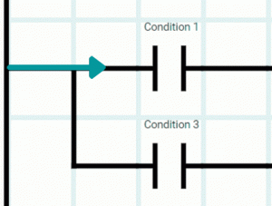
In the following example, we can appreciate that the rung contains the primary rung and a branch that connects the first two conditions with a third.

1.The hypothetical current begins on the rung’s primary branch. It analyzes the Normally Opened instruction when it gets to “Condition 1”. In this case, the N.O. instruction is TRUE so it lets the hypothetical current continue.
2.The current moves to the following N.O. instruction and tries to assess it. “Condition 2” is established to 0, which makes the N.O. instruction to return FALSE and cut off the current.
3.The result is that the hypothetical current returns to the first branch. Then, it carries out the N.O. instruction and “Condition 3”, since they are associated. “Condition 3” bit is 1 (or HIGH), so the Normally Opened instruction assesses it to TRUE. As a result, the current continues.
4.When the current gets to the Control Coil instruction, it turns the “Energize 1” bit ON.
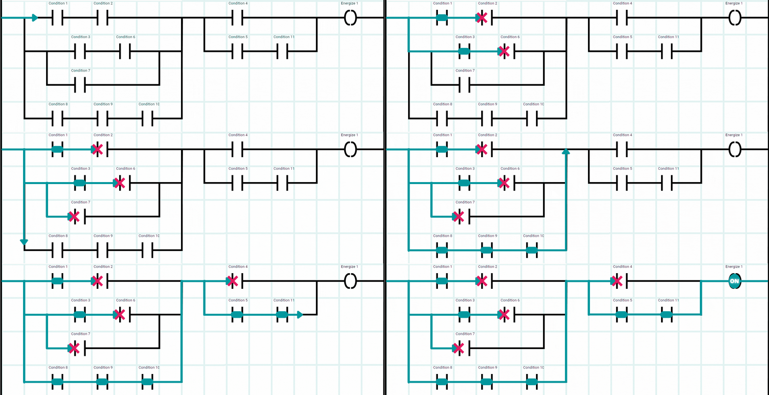
Here you have another exemple, but a bit more challenging.


